Welcome to Circuit Designer. In this tutorial, we're going to use integrated circuits.
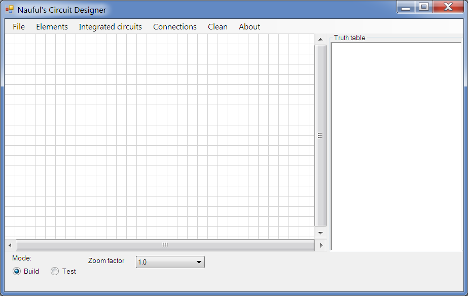 | Open CircuitDesigner. |
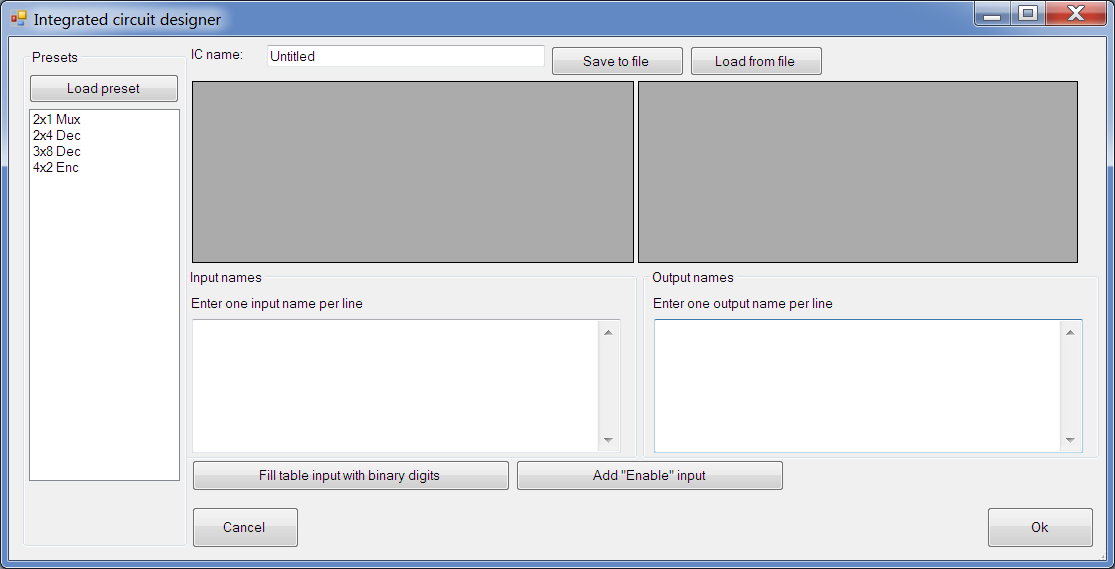 | Click on Integrated Circuits>Add |
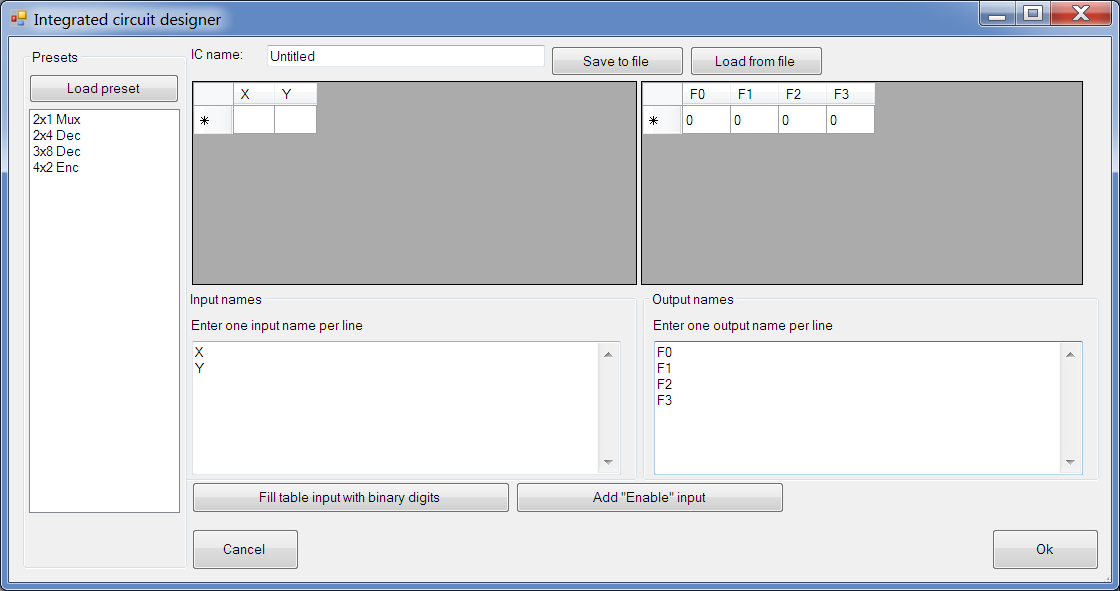 | If you like, you can load the 2x4 Dec preset, but for the purpose of this tutorial, let's start from scratch. In the input names box, enter X and then Y on the next line. Under output names, enter F0, F1, F2 and F3 each on a new line like shown. |
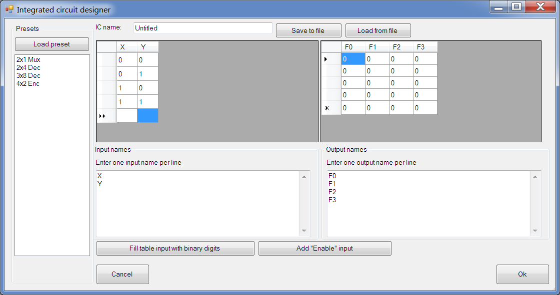 | Now enter these lines into the grid with X and Y as column names:
0 0
0 1
1 0
1 1
Your output table is automatically filled with an appropriate number of 0s. Note that x for "dont-care" can be placed in the input table if the value of that input is irrelevant in the given case. "Dont-care" can't be placed in output columns. If you want to automatically add an enable gate (adds an E column with all 1s and a row with E=0 and x in its other inputs), click on the appropriate button. There's also another button to automatically fill the input fields with binary digits. |
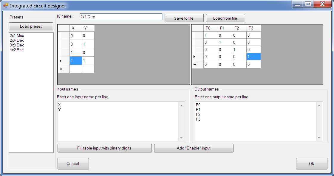 |
Enter 1s into the output table, like a 2x4 Decoder's truth table's output portion. Then, change the IC name from "Untitled" to "2x4 Dec". You can save this to file for future use, or load an existing IC file. Click OK. |
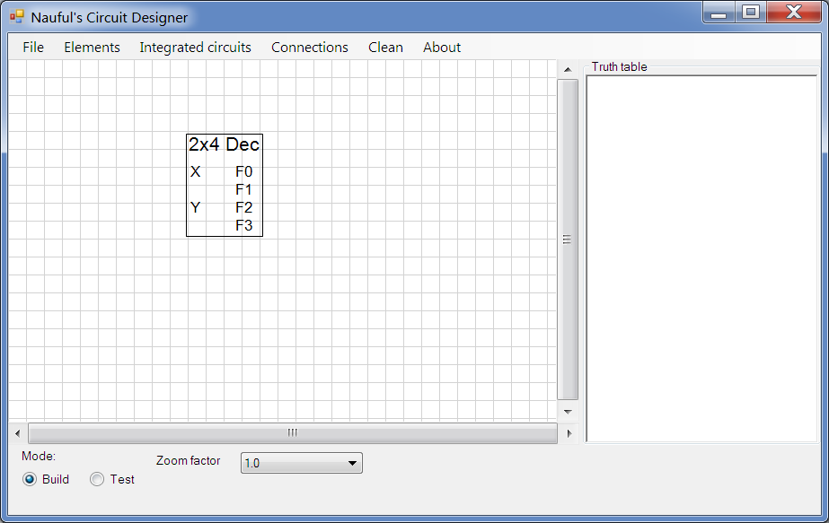 | Now, click to place your IC. If you want to modify an existing IC, go to Integrated Circuits>Modify and then click on it. |
 | Add some inputs. |
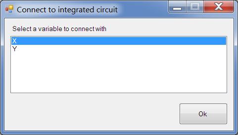 | Connect them to your IC. A dialog box will ask you which input to connect to. |
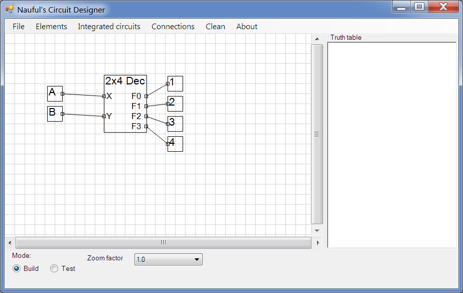 | Add some outputs and connect them in order, in the same manner. |
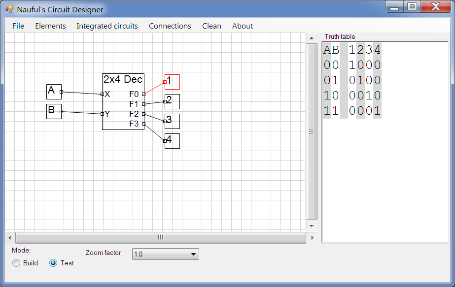 | Now switch to build mode and try it out. |
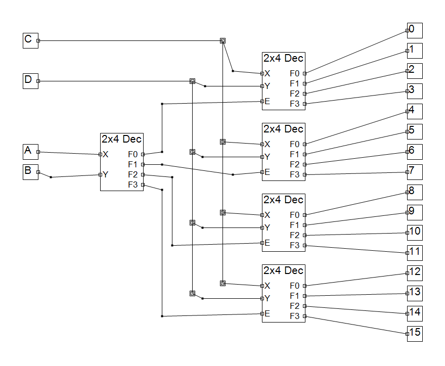 | It's also possible to chain ICs together just by connecting them like inputs/outputs. Here, I have made a 4x16 decoder with five 2x4 decoders. I saved this image from File>Save Image. You can also copy it to the clipboard from the same menu. |