

Welcome to Circuit Designer. In this tutorial, we're going to build a simple XOR gate, then we're going to build a half adder.
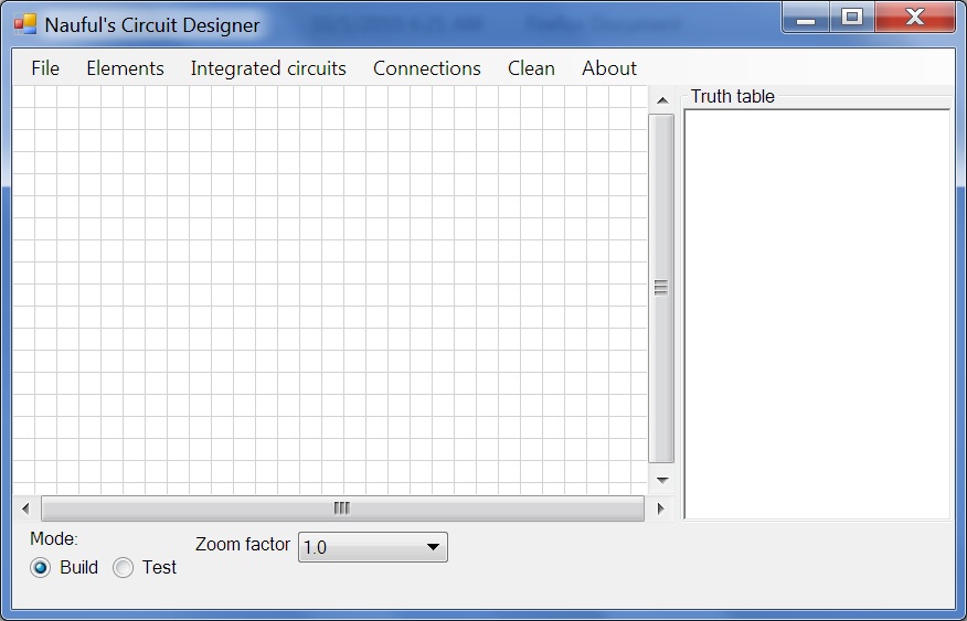
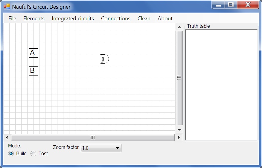
| The starting window. Let's start by placing two inputs. |
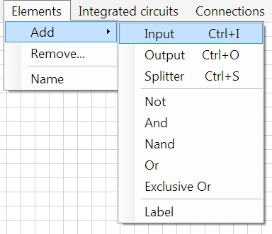
| Note that Ctrl+I is the keyboard shortcut for placing an input. We'll use this for the second input. After clicking on Elements>Add>Input or Ctrl+I on your keyboard, click on the grid to place this input. After placing it, you can click and drag it to move it. |
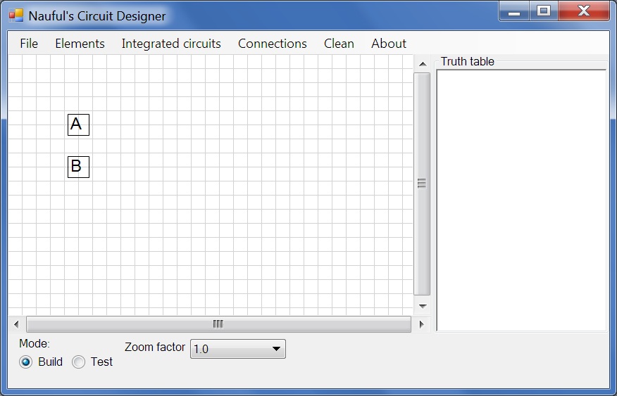
| Place another input below the first as shown. |
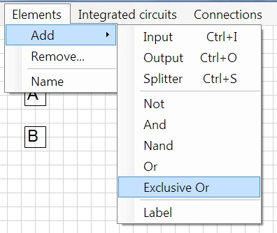
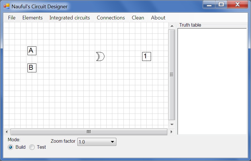
| Now select an exclusive OR gate and place it on the right-hand side. |
| Next, we should add an output. It can be found on the same menu (Elements>Add) or with the keyboard shortcut Ctrl+O. Place it on the right of the XOR gate. |
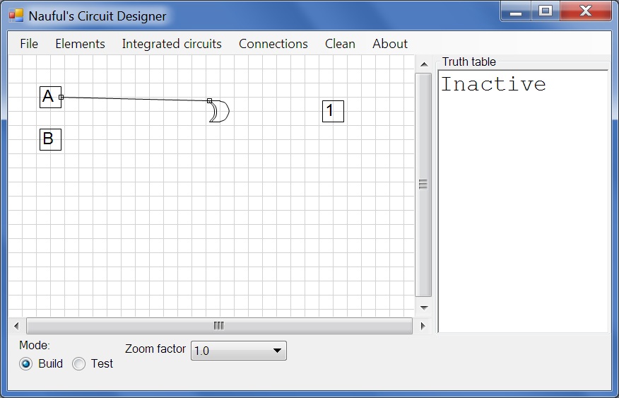
| This circuit needs to be connected. Go to the Connections menu and click on Connect, or use the keyboard shortcut Ctrl+C. It will say "Select output", click on the input marked "A". It will then say "Select input", click on the OR gate. |
| Go ahead and connect B to the XOR gate, then the XOR gate to 1. You have to click on the source/output first, then the destination/input. |
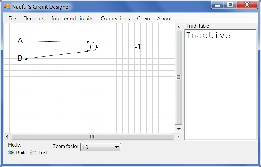
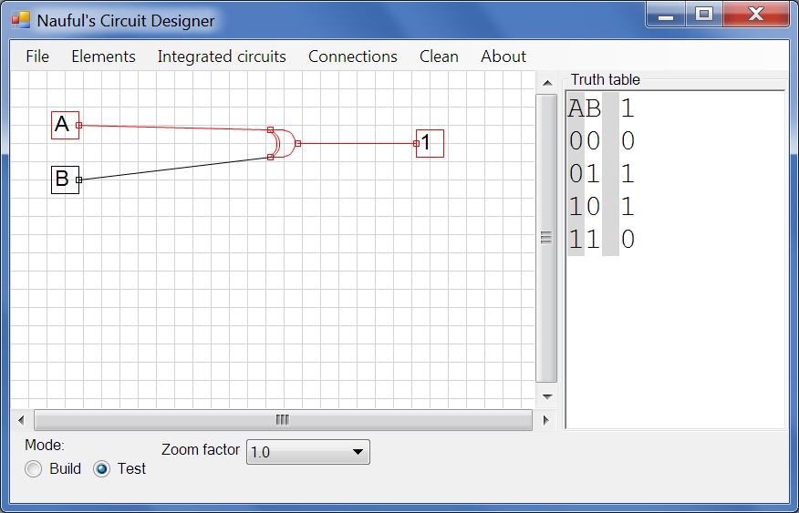
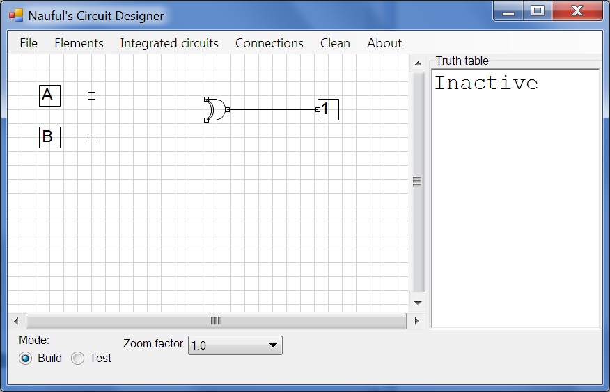
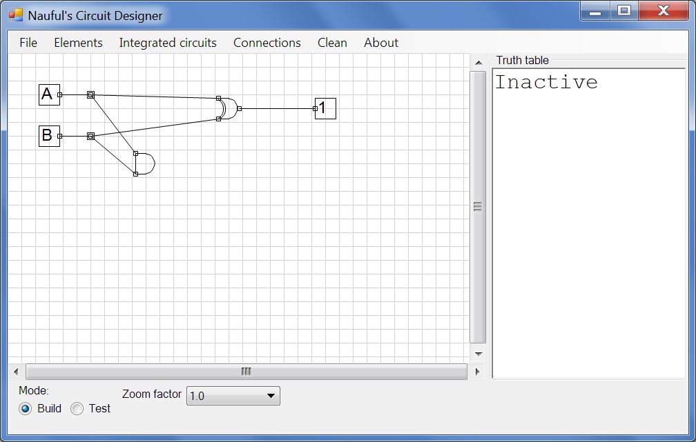
| Your circuit should now look like this. Click on the Test radio button. |
| In this mode, the truth table is displayed. Click on an input to toggle it. Here, I've toggled A but not B, so the XOR gate passes. The red colour denotes flow. Return to build mode so we can continue onto building a half adder. |
| Disconnect the connections A, XOR and B, XOR by going to Connections>Disconnect or use the keyboard shortcut Ctrl+D and then click on the lines connecting the XOR gate with A and with B. We need to split the output of A and output of B, so go to Elements>Add>Splitter or use the keyboard shortcut Ctrl+S and place two splitters, one next to A on its right side and one next to B, also on its right side. |
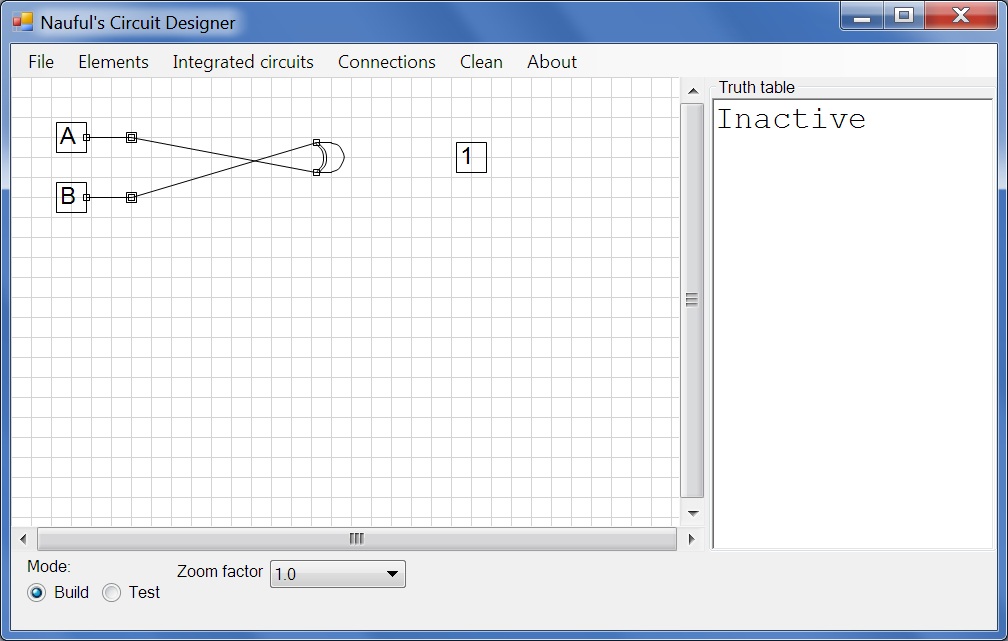
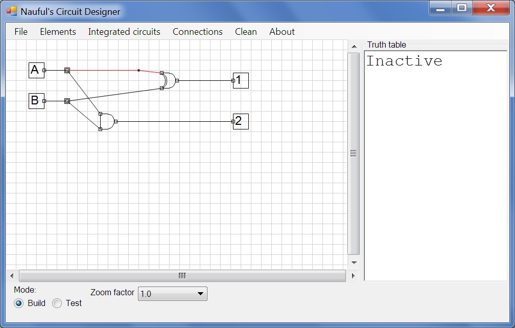
| A splitter splits a connection. Connect A to its splitter, then the splitter to the OR gate.Do the same for B. In this screenshot, my inputs are crossed because I connected B before A, to fix this, just click on Clean. |
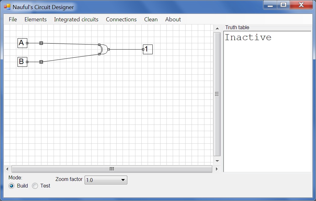
| Clean rearranges connections to simplify the graph, moves everything up and realigns inputs. |
| Connect the XOR gate to the output like shown. |
| Add an AND gate and connect the two splitters to it. |
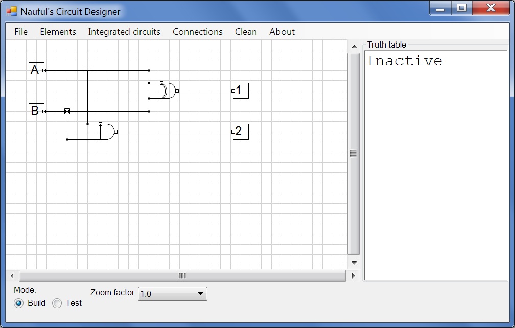
| Add another output and connect the AND gate to it. Now we're going to clean up the connections. Click on Connections>Segments>Add and then click anywhere on the line connecting A's splitter to the XOR gate. |
| Then drag the point to this position. The line is red because it's currently selected. You can now add split points on the left or right side of this point on the line if you need more. Do the same for the other connections. Click and drag on these points or on elements to move them around and tidy up. |
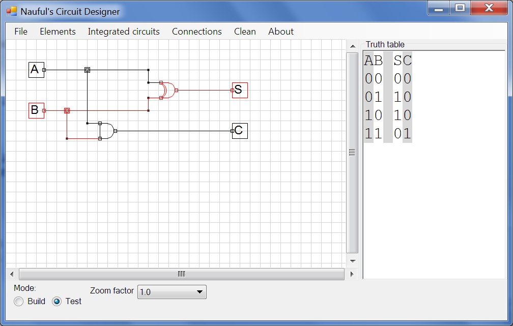
| The last step is to rename our outputs. Click on Elements>Name, click on 1 and enter S. Name the other output C. Then go to the Test mode. |
| You now have a functional half adder. Go to File>Save to save your circuit. |